 Email:
  Telephone: +86-0514-85086085
 FAX: +86-0514-85086085
 English
 中文简体
中文简体 русский
 عربى
عربى
A petrochemical plant in eastern China spent two weeks chasing intermittent 4-20 mA transmitter errors. Every diagnostic pointed to the instrument, yet every bench test passed. The fault was the cable: a parallel-pair PVC-jacketed type converted magnetic field noise from adjacent variable-frequency drive feeders into a live differential error. Replacing it with a twisted pair instrumentation cable eliminated the problem in eight hours.
The reason is not exotic. A twisted pair instrumentation cable is a transmission line built around geometry: two insulated conductors are twisted together with a controlled lay length so that, in a differential receiver, interference coupled to both conductors appears as a common-mode signal and is cancelled at the subtraction stage. Differential signal transmission works because the receiver measures the voltage difference between the pair, not between each conductor and ground.
Content
- 1 What Differential Signaling Requires From a Twisted Pair Instrumentation Cable
- 2 How Twisting a Pair Cancels Noise Before It Reaches the Receiver
- 3 Shielded or Unshielded Twisted Pair: What the Application Really Decides
- 4 Capacitance and Insulation: The Hidden Specs in a Differential Cable
- 5 How to Choose a Twisted Pair Instrumentation Cable for a New Project
- 6 Frequently Asked Questions
What Differential Signaling Requires From a Twisted Pair Instrumentation Cable
Differential signaling can function over almost any two-conductor cable, but it becomes dependable only when the pair is electrically and geometrically balanced.
In a balanced differential link, the driver sends equal and opposite currents down wire A and wire B. The receiver amplifies the difference A minus B. Any voltage that appears identically on both wires, whether AC ripple, motor noise, or ground shift, is rejected. The critical phrase is "appears identically," and that is where the cable decides the outcome.
Core definition: a twisted pair instrumentation cable is a balanced two-conductor transmission medium in which twist pitch, conductor resistance, and capacitance symmetry are controlled so that external electromagnetic fields induce nearly identical voltages on both conductors, enabling the differential receiver to reject them as common mode.
An unbalanced cable breaks that symmetry in several measurable ways:
- Unequal conductor resistance or loose terminations create a DC offset that consumes part of the receiver noise margin.
- Irregular twist pitch allows the same magnetic source to induce more voltage in one conductor than the other, producing differential-mode noise.
- Capacitance unbalance between the two conductors converts common-mode voltage transients into a false differential signal.
- Impedance discontinuities from inconsistent spacing cause reflections that distort fast digitized waveforms.
The table below maps each balanced-pair requirement to the failure a maintenance team will actually see in the field.
| Balanced-pair requirement | Field failure symptom | Signal integrity impact |
| Matched conductor resistance | DC offset at receiver input | Reduced noise margin at the far end of the cable |
| Uniform twist lay length | Noise spikes synchronized with motor drives | Common-mode noise converted into differential error |
| Capacitance balance | Transient errors when contactors open | Common-mode transients translated into spikes |
| Stable characteristic impedance | Pulse ringing on RS-485 links | Bit errors and shorter reliable cable length |
Field note: if a differential loop produces errors only when a large drive starts, suspect the cable geometry before the instrument. A new transmitter with a weak signal will behave identically on the same pair.
How Twisting a Pair Cancels Noise Before It Reaches the Receiver
Twisting is the most cost-effective noise countermeasure because it converts magnetic pickup into a common-mode voltage at the receiver.
Each complete twist reverses which conductor is closer to an external noise source. The induced voltage from one half-turn opposes the induced voltage from the next half-turn, so over the full run the contributions cancel. At the same time, the compact spiral reduces the effective loop area exposed to magnetic flux. This is why RS-485 fieldbus survives in industrial plants where single-ended links over parallel cable fail.
Classic length-versus-data-rate curve for RS-485 over balanced twisted pair, based on TIA/EIA-485 guidance.
RS-485 distance limits follow a simple rule:
- 100 kbps: up to 1200 m of twisted pair cable,
- 1 Mbps: up to 120 m,
- 10 Mbps: up to 12 m.
These distances are achievable only while the pair remains balanced and the terminations match the cable characteristic impedance.
Shielded or Unshielded Twisted Pair: What the Application Really Decides
Shielding complements twisting; it does not replace it.
For electrostatic coupling from nearby power cables, a foil or braid shield is the first defence. For magnetic field coupling from motor feeders, transformers, and ground loops, the twist is the primary defence. The most reliable industrial instrument circuits use both: a twisted core assembly under an overall shield, with a drain wire and a single-point ground.
Unshielded twisted pair
- Lowest capacitance and simplest termination
- Good common-mode rejection in clean electrical areas
- Requires strict separation from high-energy cables
Shielded twisted pair
- Adds electrostatic protection from 60 Hz to radio-frequency noise
- Preferred near VFDs, welders, and high-voltage switchgear
- Needs disciplined single-point grounding to avoid shield current noise
In hazardous areas the decision also involves safety parameters. An intrinsically safe circuit limits stored energy in the cable; capacitance and inductance per metre are safety-rated values, not just signal quality figures. A computer control cable for intrinsically safe circuits is built with controlled twist, low-capacitance insulation, and an overall screen to satisfy both signal integrity and ignition protection requirements.
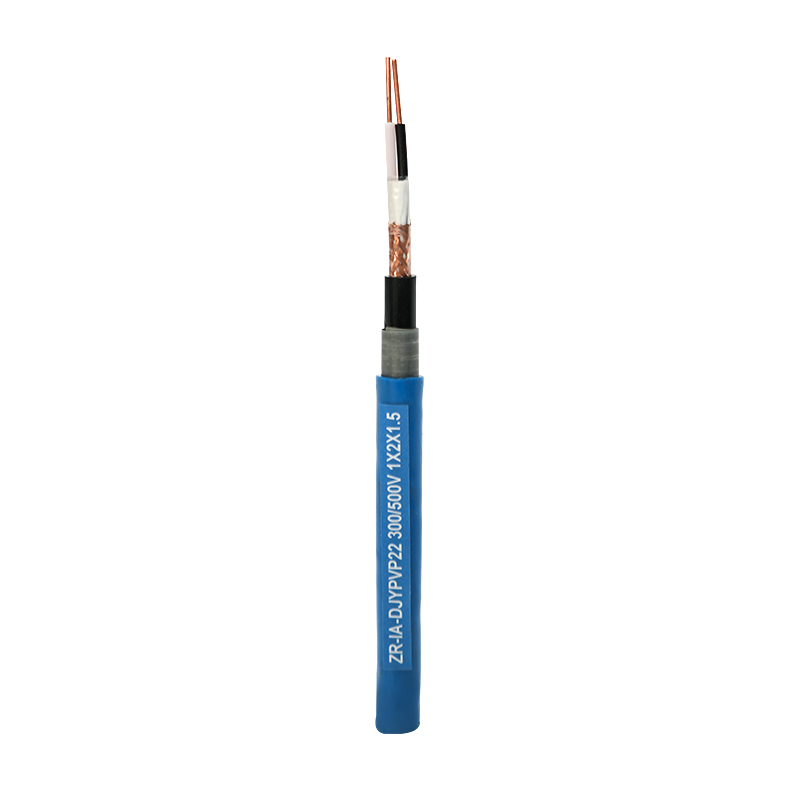 Intrinsically Safe Computer Control Cable for Hazardous AreasThis cable is designed for intrinsically safe circuits, using controlled twist, low-capacitance insulation, and an overall screen to meet both signal integrity and ignition protection requirements. It suits oil, chemical, and coal mine control systems.View Product →
Grounding rule: with large potential differences between plant earths, a shield grounded at both ends becomes a noisy conductor. Ground the shield at one end, usually the control-room side, unless the cable and system designer jointly specify a different scheme.
Capacitance and Insulation: The Hidden Specs in a Differential Cable
For differential transmission, mutual capacitance between the two conductors directly sets the maximum cable length and waveform quality.
Every metre of pair adds capacitance that the driver must charge and discharge. Higher capacitance increases rise time, narrows the eye opening, and shortens the usable distance at a given data rate. Insulation material is the largest factor. PE and FEP have dielectric constants around 2.1 to 2.4, while PVC sits near 3.5 to 4.5. A PE-insulated computer cable therefore offers roughly half the capacitance of a PVC-insulated design with the same geometry.
- PE-insulated pair: low capacitance, stable signal speed, continuous temperature rating around 70 to 90 C.
- FEP or PTFE-insulated pair: low capacitance plus high temperature rating of 200 C and above.
- PVC-insulated pair: mechanically tough but high capacitance, better for short control runs.
Selection tip: a PE-insulated computer cable is the standard starting point when an analog or digital differential signal must travel more than 50 metres through tray or conduit with limited separation from other circuits.
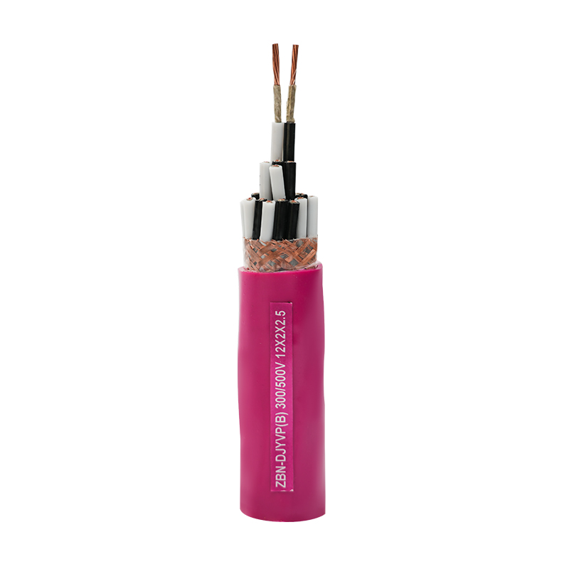 PE Insulated Computer Cable for Long-Run Differential SignalsWhen analog or digital signals must travel over 50 metres with limited separation, this PE-insulated cable provides low-loss transmission and stable performance. It supports DCS, electronic computer, and automation control systems at rated voltages up to 450/750V.View Product →
When ambient temperatures exceed the capabilities of PE, a fluoroplastic-insulated computer cable preserves low capacitance while surviving steam lines, furnace walls, and hot manufacturing areas.
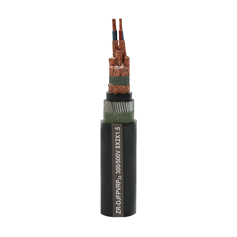 Fluoroplastic Insulated High-Temperature Computer CableFor environments exceeding PE temperature limits, this fluoroplastic-insulated cable preserves low capacitance while resisting heat, corrosion, oil, and flame. It suits steam lines, furnace walls, and hot manufacturing areas for reliable signal transmission.View Product →
Datasheet check: look for three numbers on the instrumentation cable datasheet - mutual capacitance in pF/m, capacitance unbalance in percent, and twist lay length in mm. If a manufacturer cannot state them with a tolerance, the product is not a true instrumentation cable.
How to Choose a Twisted Pair Instrumentation Cable for a New Project
Start with the signal standard and the electromagnetic environment, not with the cable price per metre.
The selection process can be compressed into six decisions, in order of importance:
Identify signal type
4-20 mA analog, RTD, RS-485, HART, or a digital bus.
Define the noise environment
VFD feeders, welding loads, contactor-heavy panels, or long parallel runs.
Check hazardous area rating
Intrinsic safety requires entity parameters such as capacitance and inductance limits for the cable.
Confirm mechanical constraints
Tray, conduit, flexing, UV exposure, and ambient temperature all change insulation and jacket choice.
Match twist and shield to the bus
RS-485 and HART work on twisted pairs; high-speed digital links need a controlled impedance and a tighter lay.
Request the measured values
Ask for twist pitch, mutual capacitance, capacitance unbalance, and shield transfer impedance in writing.
Final rule: the answer always starts with the receiver and the noise source, then the cable geometry, then shielding and insulation.
For specification help and test documentation on multiple instrumentation cable families, Yangzhou Yaguang Cable Co., Ltd. publishes selection guidance on its company profile and manufacturing standards.
Frequently Asked Questions
Is shielding still necessary if the pair is already twisted?
Yes, for most industrial installations. Twisting handles magnetic field coupling and common-mode balance; shielding handles electrostatic coupling from nearby power conductors. In environments with VFDs or switchgear, use a shielded twisted pair grounded at a single point.
What does twist lay length mean and why does it matter?
Twist lay length is the distance along the cable needed for the two conductors to complete one full revolution. A shorter lay length reduces loop area and improves noise rejection, but it adds capacitance and cost. A longer lay length is cheaper and lower capacitance but less effective against magnetic pickup.
Can a short parallel-pair run work for a differential signal?
Yes, if the run is short and the environment is clean. The problem appears when the run passes beside motor cables, contactors, or high-voltage circuits. Once common-mode pickup is converted into differential error by an unbalanced pair, no receiver gain can remove it.
Why is capacitance unbalance specified on instrumentation cable datasheets?
Capacitance unbalance is the percentage difference in capacitance between the two conductors or between each conductor and screen. If one conductor stores more charge than the other, common-mode transients appear as differential voltage. Low unbalance directly improves common-mode noise rejection.
When in doubt, ask for the cable mutual capacitance, capacitance unbalance, twist pitch, and shield transfer impedance. A real instrumentation cable manufacturer should have all four values measured and documented.
 Email:
 Telephone:+86-0514-85086085
 FAX:+86-0514-85086085
 Phone:+86-15861389306