 Email:
  Telephone: +86-0514-85086085
 FAX: +86-0514-85086085
 English
 中文简体
中文简体 русский
 عربى
عربى
Inside a polymer processing plant, a 150 kW variable frequency drive ramps up every 90 seconds. Each time it does, a nearby 4-20 mA pressure transmitter drifts by 2.3 mA for roughly 400 ms, enough to trigger a false high-level alarm and stop the extruder line. The transmitter is not faulty. Electrical noise is coupling into an unshielded instrument loop, and the practical fix is a shielded instrumentation cable that drains interference before it reaches the signal pair.
Signal integrity in an industrial environment is the ability of a transmitted signal to arrive at the receiver within its specified amplitude, timing, and frequency tolerances. When motors, drives, contactors, and welders share cable trays, holding those tolerances demands a cable engineered to reject interference, not just a better transmitter.
Content
- 1 Three Coupling Mechanisms That Break Signal Integrity
- 2 How a Shielded Instrumentation Cable Blocks Electrical Noise
- 3 Foil, Braid, or Combination: Matching the Shield to the Noise
- 4 Why Twisted Pairs Complement the Shield in Instrument Cables
- 5 Grounding Rules That Keep a Shield Quiet, Not Noisy
- 6 How to Select a Shielded Instrumentation Cable That Passes Field Tests
- 7 Shielded Instrumentation Cable: Common Field Questions
Three Coupling Mechanisms That Break Signal Integrity
Three coupling mechanisms account for nearly all signal-integrity failures in industrial instrument loops: capacitive coupling, inductive coupling, and common-impedance coupling. Fixing only one of the three rarely restores a clean measurement.
- Capacitive coupling. A changing voltage (dV/dt) in an adjacent power conductor injects displacement current through the distributed capacitance between cables. A 400 V drive output switching at 4 kHz can inject enough current to disturb a high-impedance instrument input mounted meters away.
- Inductive coupling. A changing current (di/dt) creates a magnetic field that induces voltage in the loop area formed by the signal pair. The larger that loop, the higher the induced voltage.
- Common-impedance coupling. Noise current returning through a shared earth or tray bond develops voltage across that impedance, and that voltage appears in series with the signal at the receiver.
How a Shielded Instrumentation Cable Blocks Electrical Noise
A shielded instrumentation cable blocks noise by intercepting interfering energy on the shield boundary and conducting it to ground before the signal conductors see it. The shield is a continuous conductive envelope around the twisted pair, and it does three jobs at once.
- Reflection. The impedance mismatch at the air-to-metal boundary reflects most radiated energy back into the surroundings. A copper braid with 85 percent coverage typically reflects well over 95 percent of incident electric-field energy in the 30-100 MHz range.
- Absorption. At high frequency, skin effect forces the remaining field onto the outer surface of the shield, where it decays exponentially. Skin depth in copper is about 66 micrometers at 1 MHz, so even a thin foil layer dissipates significant energy.
- Drainage. The intercepted noise travels along the shield or its drain wire to the grounding point and returns to its source instead of entering the signal circuit.
Foil, Braid, or Combination: Matching the Shield to the Noise
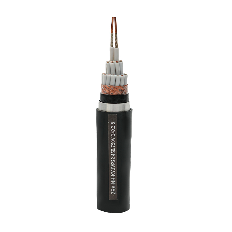
Foil shields give full coverage and handle electric-field noise. Braid shields give low resistance and rugged termination. Combination shields deliver broadband performance but cost more and bend less. For VFD-heavy plants, the combination is usually worth the extra cost.
| Construction | Coverage | Attenuation at 100 MHz | Flexibility | Termination |
| Aluminum foil | 100% | 55-65 dB | High | Drain wire |
| Copper braid | 85-90% | 65-75 dB | Medium | Direct clamp |
| Foil plus braid | ~100% | 85-95 dB | Lower | Drain plus clamp |
| Double screen | 100% | 95+ dB | Lowest | Bonded glands |
Why Twisted Pairs Complement the Shield in Instrument Cables
Twisting rejects magnetically induced noise by equalizing the loop area of the two conductors, while the shield rejects electric-field noise. The two defenses are complementary: the twist handles the magnetic term, the shield handles the capacitive term, and neither one alone is enough in a busy tray.
Each twist flips the orientation of the exposed loop, so the voltages induced in adjacent half-turns cancel at the receiver. The shorter the twist lay length, the better the rejection. A 25 mm lay, common in instrument pairs, rejects far more magnetic interference than the 75-100 mm lay typical of control pairs.
Insulation material also shapes signal quality. A polyethylene (PE) insulation with a dielectric constant near 2.3 reduces capacitive loading compared with PVC at about 3.5, which preserves the edges of digital signals and lowers noise pickup. That makes it the standard approach when the run also carries communication between the control system and field electronics.
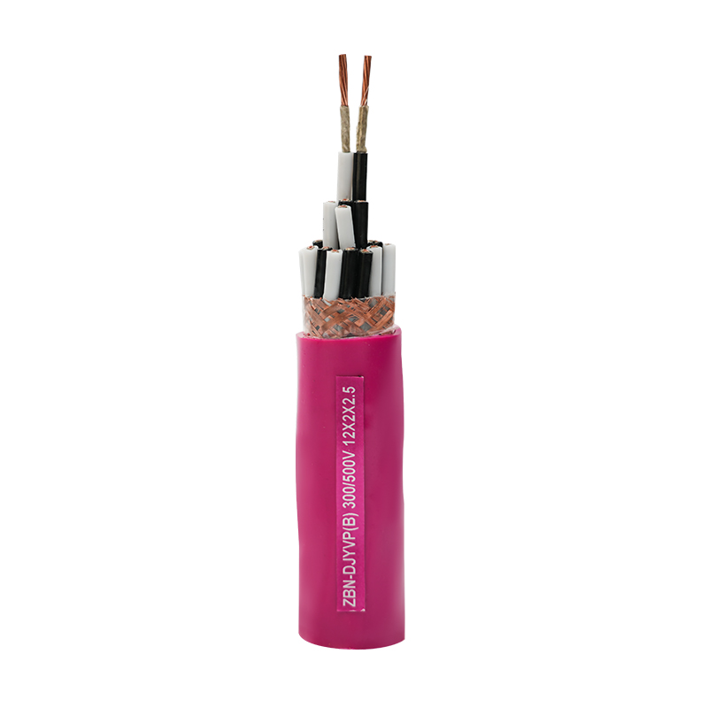 PE Insulated Computer Cable for Low-Loss Signal TransmissionThis cable uses polyethylene insulation with a low dielectric constant, reducing capacitive loading and preserving digital signal edges. It suits industrial control and DCS applications requiring stable data transmission and shielding options.View Product →
Grounding Rules That Keep a Shield Quiet, Not Noisy
Correct grounding decides whether a shield protects the signal or amplifies the noise. For instrument loops, one ground point at the reference end is the standard, not two.
- Ground the shield at one end only. Two grounds create a loop, and the difference in earth potential drives current through the shield and couples into the pair.
- Choose the reference end. Ground at the receiver when the loop reference is the control system; ground at the sensor when the measurement is referenced in the field.
- Keep the drain wire short. A long pigtail adds inductance and reduces high-frequency shield performance; trim it to the minimum needed length.
- Treat hazardous-area circuits separately. Intrinsically safe loops need certified cable constructions and grounding that follows the associated apparatus documentation, not general practice.
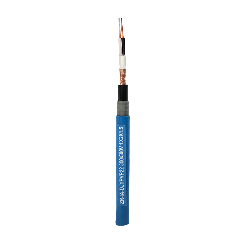 Intrinsically Safe Computer Control Cable for Hazardous AreasDesigned for explosive environments, this cable features low capacitance and inductance with effective shielding to prevent sparks. It is suitable for DCS and automation systems in oil, chemical, and mining plants.View Product →
How to Select a Shielded Instrumentation Cable That Passes Field Tests
Selection starts with the noise spectrum and ends with mechanical and compliance validation: attenuation target, pair construction, insulation, certification, and manufacturer test data.
- Identify the dominant interference frequency. VFD harmonics sit mainly below 1 MHz; choose foil for low frequency, braid for ruggedness, and foil-plus-braid for broadband coverage.
- Set an attenuation target in dB at that frequency. A 60 dB floor is a reasonable minimum; 90 dB suits trays loaded with several drives.
- Match the insulation to the environment. PE for low capacitance, PVC for general duty, fluoroplastic for high temperature and corrosive atmospheres.
- Verify certifications against your plant standard, including flame propagation, marine, or intrinsic safety requirements.
- Check capacitance and long-loop voltage drop before committing to long drum lengths.
For high-temperature and corrosive installations, a fluoroplastic insulation keeps the same pair geometry and shield performance where PVC and PE soften and fail.
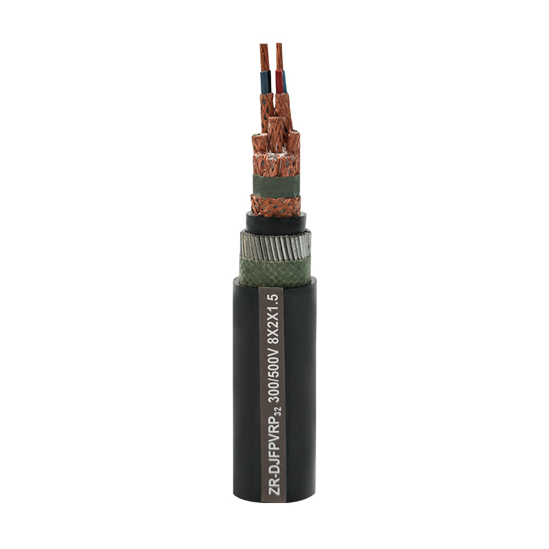 Fluoroplastic Insulated Computer Cable for Extreme ConditionsWith fluoroplastic insulation, this cable withstands high and low temperatures, corrosion, and flame, maintaining signal integrity where PVC and PE fail. Ideal for aerospace, petrochemical, and harsh industrial environments.View Product →
Yangzhou Yaguang Cable Co., Ltd., a specialty cable manufacturer with more than 25 years of production experience, publishes detailed specifications for shielded instrumentation and computer cables across PE, PVC, and fluoroplastic insulation families. Compare those datasheets against the five criteria above before you order.
Shielded Instrumentation Cable: Common Field Questions
Short answers to the questions engineers ask most often when specifying and commissioning shielded instrumentation cable.
Should a shielded instrumentation cable be grounded at both ends?
No, for most loops. Grounding both ends lets circulating current flow through the shield, and the resulting voltage drop couples into the pair. Ground one end only, normally at the receiver reference, unless the plant standard specifies multi-point grounding for an unusual interference spectrum.
Is foil or braid better for instrumentation cable?
Neither is universally better. Foil gives 100 percent coverage and strong electric-field rejection but needs a drain wire. Braid gives a heavy, low-resistance path and survives trays better, yet its coverage stops near 85 to 90 percent. A combination shield is the strongest choice when VFD noise is present.
Can shielding fix a ground loop already present in a control loop?
Only if the loop is re-grounded correctly. A shield connected at two points adds a parallel path that may make the problem worse. Isolate the drain to one reference point and verify the millivolt level at the receiver input.
How is shielded instrumentation cable different from shielded control cable?
Instrumentation cable uses twisted pairs with matched lay lengths, lower capacitance, and tighter shield tolerance to preserve analog and low-level digital signals. Control cable delivers power to contactors and valves, where durability matters more than signal fidelity.
 Email:
 Telephone:+86-0514-85086085
 FAX:+86-0514-85086085
 Phone:+86-15861389306