 Email:
  Telephone: +86-0514-85086085
 FAX: +86-0514-85086085
 English
 中文简体
中文简体 русский
 عربى
عربى
Content
- 1 What Is Instrumentation Cable
- 2 What Instrumentation Cable Is Used For
- 3 How Instrumentation Cable Works
- 4 Instrumentation Cable Construction and Structure
- 5 Instrumentation Cable Types and Applications
- 6 Shielded Instrumentation Cable Explained
- 7 Twisted Pair Instrumentation Cable Benefits
- 8 Instrumentation Cable Shielding Types
- 9 Instrumentation Cable Specifications Guide
- 10 How to Choose Instrumentation Cable
What Is Instrumentation Cable
Instrumentation cable is a low-voltage cable specifically engineered to carry signals between field instruments — sensors, transmitters, controllers — and control systems in industrial and process environments, with a primary design focus on protecting weak, precision signals from electrical noise and interference rather than delivering power. It's a distinct category from power cable, which is designed to carry current efficiently, and from data cable, which is optimized for high-speed digital transmission.
These cables typically carry small analog signals (such as 4-20mA current loops), low-voltage digital signals, or thermocouple and RTD temperature signals, all of which are highly sensitive to electromagnetic interference from nearby power cables, motors, and variable frequency drives commonly found in industrial settings.
What Instrumentation Cable Is Used For
- Connecting process sensors (pressure, temperature, flow, level) to control room instrumentation
- 4-20mA analog current loop signal transmission between field transmitters and PLCs/DCS systems
- Thermocouple and RTD temperature sensor wiring in process plants
- Low-voltage control and monitoring circuits in oil and gas, power generation, water treatment, and manufacturing facilities
- Fieldbus and communication protocol wiring where signal integrity directly affects process control accuracy
How Instrumentation Cable Works
Instrumentation cable protects signal integrity through a combination of conductor pairing, shielding, and physical construction, rather than through any special property of the copper conductor itself. Twisted conductor pairs cancel out induced electromagnetic interference through a principle where noise picked up equally on both wires of a twisted pair is rejected at the receiving instrument, since it appears as a common-mode signal rather than a differential one carrying the actual signal.
Shielding adds a second layer of protection by providing a conductive barrier — typically foil or braided copper — around the conductor pairs, which intercepts external electromagnetic fields and, when properly grounded at one end, drains induced noise to ground before it can couple onto the signal conductors.
Instrumentation Cable Construction and Structure
| Layer | Function |
|---|---|
| Conductor | Typically stranded copper, carries the signal current |
| Insulation | PVC, PE, or other dielectric material isolating each conductor |
| Twisted pair configuration | Two insulated conductors twisted together to cancel induced noise |
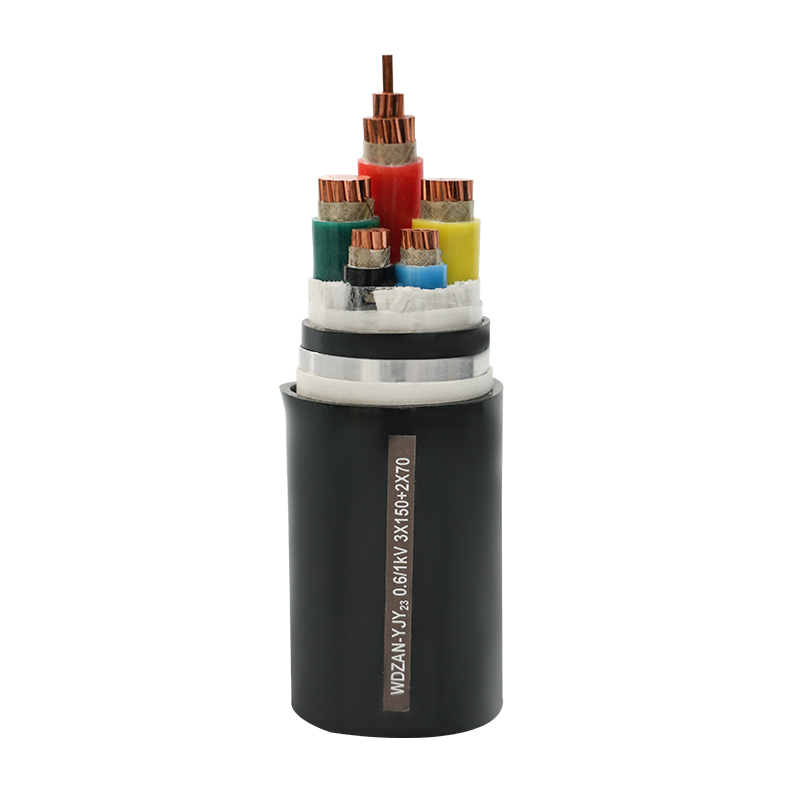
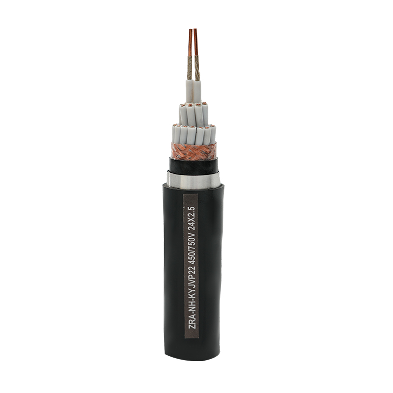
| Shield | Foil or braided copper layer blocking external EMI/RFI |
| Drain wire | Bare conductor in contact with the shield, used for grounding termination |
| Outer jacket | PVC, PE, or specialty compound protecting against environmental exposure |
Instrumentation Cable Types and Applications
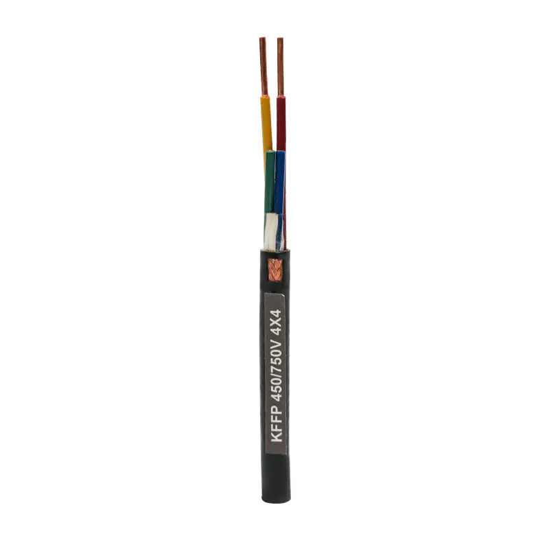
- Single pair cable: one signal circuit, used for simple point-to-point instrument connections
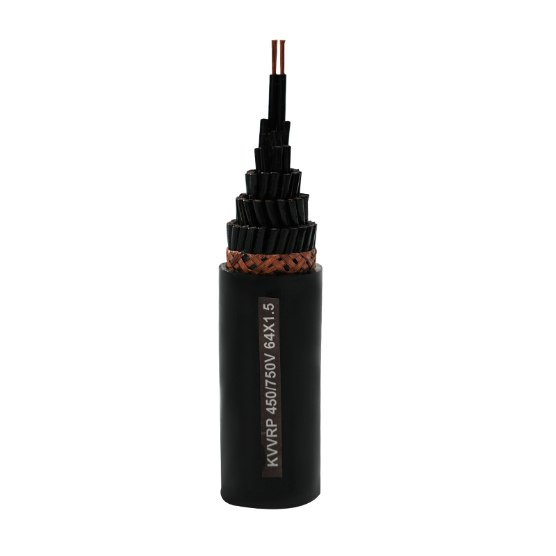
- Multi-pair cable: multiple twisted pairs bundled in one jacket, used where many instruments route back to a common control panel
- Triad cable: three conductors twisted together, used for signals requiring a dedicated reference or ground conductor per circuit
- Thermocouple extension cable: uses conductor alloys matched to specific thermocouple types to preserve temperature signal accuracy
- Fieldbus cable: constructed to meet specific impedance and capacitance requirements for digital fieldbus communication protocols
Shielded Instrumentation Cable Explained
Shielding is what separates instrumentation cable from general-purpose low-voltage wiring, and it exists specifically to block electromagnetic and radio-frequency interference from coupling onto sensitive signal conductors. The shield only works effectively when grounded correctly — typically at one end only, to avoid creating a ground loop that would itself introduce noise into the circuit rather than eliminate it.
Foil shields offer close to 100% coverage against high-frequency interference and are lighter and lower-cost, while braided shields offer better mechanical durability and lower resistance at lower frequencies, though typically with slightly less coverage than a well-applied foil shield. Some cable constructions combine both — a foil shield with an overlying braid — for applications facing both high-frequency noise and demanding mechanical or flexing conditions.
Twisted Pair Instrumentation Cable Benefits
Twisting conductor pairs together provides noise rejection through a purely geometric mechanism: any interference source couples nearly equally onto both conductors of a tightly twisted pair, since they occupy essentially the same physical location relative to the noise source at any given point along the cable. Because the receiving instrument reads the difference between the two conductors, equally induced noise cancels out, while the actual differential signal passes through unaffected.
Twist rate (the number of twists per unit length) affects how well this cancellation works at different interference frequencies — tighter twists generally provide better rejection of higher-frequency noise, which is why cables intended for high-noise environments or high-frequency digital signals often specify a tighter, controlled twist rate rather than a generic loose twist.
Instrumentation Cable Shielding Types
| Shield Type | Characteristics |
|---|---|
| Foil shield | Near-100% coverage, lightweight, best for high-frequency EMI |
| Braided shield | Durable, flexible, lower resistance, good for lower-frequency noise |
| Combination foil + braid | Broadest frequency protection with added mechanical durability |
| Overall shield (multi-pair) | Single shield around the whole cable bundle, protects against external noise |
| Individual pair shielding | Each pair separately shielded, protects against crosstalk between pairs in multi-pair cable |
Instrumentation Cable Specifications Guide
Specifying instrumentation cable accurately requires matching several parameters to the signal type, environment, and installation method, rather than defaulting to a generic "signal cable" spec. Core specifications include conductor gauge, pair count and configuration, shield type, insulation and jacket material, and voltage/temperature rating.
- Conductor gauge (AWG): sized for the signal current and acceptable voltage drop over cable run length
- Pair/triad count: matched to the number of instruments or circuits being routed
- Shield type and coverage: selected based on the noise environment and frequency of interference expected
- Jacket material: PVC for general indoor use, specialty compounds (LSZH, XLPE) for hazardous, outdoor, or fire-rated applications
- Temperature and voltage rating: matched to the installation environment and signal circuit requirements
How to Choose Instrumentation Cable
Selecting instrumentation cable starts with the signal type being carried — analog current loop, low-voltage digital, or temperature sensor signal — since this determines conductor count, gauge, and whether twisted pair or twisted triad construction is appropriate. From there, assess the electrical noise environment along the planned cable route: proximity to power cables, motors, or variable frequency drives should push toward higher-coverage shielding.
- Identify signal type and required conductor/pair configuration first
- Assess electrical noise sources along the cable route to determine shielding requirements
- Match jacket material to the installation environment — indoor, outdoor, buried, or hazardous area
- Confirm compliance with relevant industry standards for the facility (fire rating, hazardous location classification)
- Verify grounding plan for the shield termination before finalizing cable selection, since improper grounding undermines shielding benefits regardless of cable quality
 Email:
 Telephone:+86-0514-85086085
 FAX:+86-0514-85086085
 Phone:+86-15861389306