 English
 中文简体
中文简体 русский
 عربى
عربىContent
- 1 What Makes Instrumentation Cable Different from Standard Wire
- 2 Shielded Instrumentation Cable: Protection Against Electromagnetic Interference
- 3 Twisted Pair Instrumentation Cable: Canceling Magnetically Induced Noise
- 4 Shielded vs Twisted Pair: Key Differences at a Glance
- 5 Shielded Twisted Pair (STP): The Common Industrial Standard
- 6 Conductor Sizing, Insulation, and Jacket Selection
- 7 Practical Selection Checklist for Instrumentation Cable
What Makes Instrumentation Cable Different from Standard Wire
Instrumentation cables are purpose-built for transmitting low-voltage analog and digital signals in industrial environments — not power. Unlike general-purpose wiring, they prioritize signal integrity over current-carrying capacity. The two most common constructions used in process control, measurement, and automation systems are shielded instrumentation cable and twisted pair instrumentation cable, and in many cases, a single cable combines both features.
Understanding the difference — and knowing when each design matters — helps engineers avoid signal errors, reduce troubleshooting costs, and meet compliance requirements from the start.
Shielded Instrumentation Cable: Protection Against Electromagnetic Interference
A shielded instrumentation cable wraps a conductive layer — typically aluminum foil (mylar), copper braid, or a combination of both — around the signal conductors. This shield acts as a Faraday cage, intercepting radiated electromagnetic interference (EMI) and radio-frequency interference (RFI) before it couples into the signal wire.
The shield must be grounded at one end (typically the receiving end) to be effective. Grounding at both ends can create a ground loop, which paradoxically introduces the low-frequency noise it was meant to eliminate.
When to specify shielded cable
- Installations near variable frequency drives (VFDs), motors, or transformers
- Long cable runs exceeding 30 meters where ambient EMI accumulates
- 4–20 mA analog loops where even millivolt-level noise causes measurement error
- Thermocouple and RTD signal wiring, which operate at very low voltages (typically under 100 mV)
- Environments with dense conduit runs where capacitive coupling between adjacent cables is a concern
Foil shields provide 100% coverage and are lighter and easier to terminate, while braid shields offer better mechanical durability and lower shield resistance — important in high-frequency applications. Combination foil-braid shields are common where both broadband coverage and physical robustness are required.
Twisted Pair Instrumentation Cable: Canceling Magnetically Induced Noise
Twisting two conductors together at a consistent lay length is one of the most effective passive techniques for rejecting magnetically induced (inductive) interference. As a changing magnetic field passes through a twisted pair, it induces equal and opposite voltages in adjacent half-twists. These voltages cancel at the receiver — a principle known as common-mode rejection.
The tighter the twist (more twists per meter), the better the rejection at higher frequencies. Standard instrumentation-grade twisted pairs typically specify 25–50 mm lay length, though this varies by manufacturer and application standard.
Where twisted pair design adds measurable value
- RS-485 and Modbus fieldbus networks, where differential signaling depends on balanced impedance
- Proximity to power cables running at 50/60 Hz, where magnetic coupling is the primary interference mechanism
- Thermocouple extension wire, where the twisted pair maintains the correct alloy pairing required for accurate temperature compensation
- HART protocol wiring, which overlays a frequency-shift-keyed signal on a 4–20 mA loop
Shielded vs Twisted Pair: Key Differences at a Glance
Both approaches reduce noise, but they target different interference mechanisms. The table below summarizes the practical distinctions:
| Feature | Shielded Cable | Twisted Pair Cable |
|---|---|---|
| Primary noise rejected | Electrostatic (capacitive) / RF | Magnetic (inductive) / common-mode |
| Mechanism | Faraday cage (requires grounding) | Differential cancellation (passive) |
| Installation requirement | Proper single-end grounding critical | No special grounding needed |
| Cost | Higher (material + termination labor) | Lower |
| Best for | High-EMI industrial environments | Differential signal buses, balanced lines |
| Combined option | Shielded twisted pair (STP) — addresses both mechanisms simultaneously | |
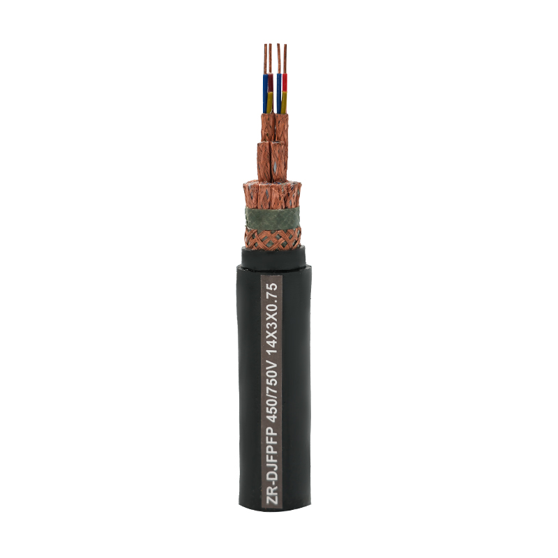
Shielded Twisted Pair (STP): The Common Industrial Standard
In most industrial instrumentation applications, shielded twisted pair (STP) cable is the default specification. Combining both technologies addresses the two most prevalent noise mechanisms simultaneously: the twist rejects magnetically coupled interference while the shield blocks electrostatically coupled EMI.
Multi-pair STP cables — such as those used in distributed control systems (DCS) and programmable logic controller (PLC) I/O wiring — typically include both an individual pair shield (IS) and an overall shield (OS). The individual shields isolate each signal pair from cross-talk with adjacent pairs, while the overall shield provides a second layer of protection against external interference.
Standards such as IEC 60332, ICEA S-73-532, and ISA-5.1 provide guidance on cable construction, conductor sizing, and application requirements. For hazardous area installations, compliance with IECEx or ATEX certifications adds additional construction requirements around jacket materials and flame retardancy.
Conductor Sizing, Insulation, and Jacket Selection
Beyond shielding and twist configuration, several other construction parameters affect cable performance in instrumentation service:
- Conductor gauge: 18 AWG (0.75 mm²) and 20 AWG (0.5 mm²) are the most common for 4–20 mA loops. Larger gauges reduce loop resistance over long runs, which matters when powering field devices from the control room.
- Insulation material: Cross-linked polyethylene (XLPE) offers superior temperature resistance (–40°C to +90°C) compared to standard PVC. For high-temperature process areas, silicone or PTFE insulation may be required.
- Jacket type: LSZH (low smoke zero halogen) jackets are required in confined or occupied spaces under standards like EN 50266. PVC jackets remain common in general industrial use due to their cost-effectiveness and oil resistance.
- Armoring: Steel wire armor (SWA) or interlocked armor provides mechanical protection for direct-burial or cable tray installations with high crush and impact exposure.
Practical Selection Checklist for Instrumentation Cable
Before specifying cable, work through these questions:
- What signal type is being transmitted — analog (4–20 mA, thermocouple), discrete, or digital fieldbus (RS-485, HART, PROFIBUS)?
- What are the dominant interference sources near the cable route — motors, VFDs, high-voltage power cables?
- What is the total run length, and does it affect permissible loop resistance or signal attenuation?
- What are the temperature extremes and chemical exposure conditions along the cable path?
- Is the installation in a classified hazardous area (Zone 1/2, Division 1/2)?
- Are fire performance requirements (flame spread, smoke density, halogen content) specified by local code or project spec?
For the majority of analog instrument loops in plant environments, a shielded twisted pair instrumentation cable with 18 AWG stranded tinned copper conductors, XLPE insulation, aluminum-foil shield with drain wire, and LSZH or PVC overall jacket will satisfy most requirements. Deviations from this baseline are driven by specific environmental, signal, or regulatory conditions.


