 English
 中文简体
中文简体 русский
 عربى
عربىContent
How to Measure Wire Size: AWG, mm², and What the Numbers Mean
Wire size is a measurement of the conductor's cross-sectional area — the amount of copper (or aluminum) available to carry current. Two systems dominate: the American Wire Gauge (AWG) standard used in North America, and the metric mm² (square millimeter) system used in Europe, Australia, and most of the rest of the world. Understanding both is essential for anyone specifying wire across international supply chains or working with imported electrical equipment.
AWG: How the American System Works
AWG is a counterintuitive system: the higher the gauge number, the smaller the wire. AWG 4 is a large conductor suitable for heavy appliance circuits; AWG 24 is the fine wire inside telephone cables. The scale originates from the number of drawing die passes required to produce the wire — more passes produce a thinner wire and a higher gauge number. The mathematical relationship is precise: each increase of 6 AWG steps halves the cross-sectional area, and each 3-step increase reduces diameter by approximately half.
To measure wire size in AWG without a datasheet, use a wire gauge tool — a flat steel plate with calibrated slots — by inserting the bare conductor into slots until finding the smallest slot it fits through cleanly. This gives the AWG directly. Alternatively, measure the bare conductor diameter with digital calipers and cross-reference against a standard AWG table: AWG 12 measures 2.053 mm diameter; AWG 14 measures 1.628 mm; AWG 10 measures 2.588 mm. Never measure insulated wire diameter — insulation thickness varies by type and voltage rating and will give an incorrect gauge reading.
Metric mm² System
The IEC metric system specifies wire size by the actual cross-sectional area of the conductor in square millimeters, which is a direct and intuitive measure of current capacity. Common residential sizes are 1.5 mm² (lighting circuits, equivalent to roughly AWG 14), 2.5 mm² (socket outlet circuits, roughly AWG 12), 4 mm² (cooker and shower circuits, roughly AWG 10), and 6 mm² (subfeeds and high-load appliances, roughly AWG 8). To calculate mm² from a measured diameter: area = π × (diameter/2)².
| AWG | Diameter (mm) | Cross Section (mm²) | Max Current (A) — Copper in Conduit | Typical Application |
|---|---|---|---|---|
| 6 | 4.115 | 13.3 | 55A | EV chargers, large subpanels |
| 8 | 3.264 | 8.37 | 40A | Electric ranges, dryers |
| 10 | 2.588 | 5.26 | 30A | Water heaters, AC units |
| 12 | 2.053 | 3.31 | 20A | Kitchen and bathroom outlets |
| 14 | 1.628 | 2.08 | 15A | General lighting and outlets |
| 16 | 1.291 | 1.31 | 13A | Extension cords, fixtures |
Current ratings in the table above reflect NEC (National Electrical Code) ampacity values for copper conductors in conduit at 60°C insulation rating and 30°C ambient temperature. Wire bundled in walls without conduit, or run in high-ambient environments, must be derated — the NEC specifies correction factors as low as 0.5× for conduits with more than three current-carrying conductors. Undersized wire does not simply fail immediately — it overheats slowly, degrading insulation over months or years until a fault or fire occurs.
How Copper Wire Is Produced: From Cathode to Finished Conductor
Copper wire production is a multi-stage industrial process that begins with refined copper cathodes — flat plates of 99.99% pure copper produced by electrolytic refining of smelted ore — and ends with finished conductors drawn to precise diameters, annealed to the correct temper, and wound onto reels for insulation or direct sale. The global wire and cable industry consumes approximately 28 million metric tonnes of copper per year, making it the largest single end-use category for the metal.
Step 1: Continuous Casting into Rod
Copper cathodes are melted in a shaft furnace or induction furnace at approximately 1,085°C (the melting point of copper) and cast into continuous rod through a process called Properzi or CONTIROD casting, developed in the mid-20th century specifically for the wire industry. Molten copper is poured into a moving mold formed by a grooved casting wheel and a steel belt, solidifying into a continuous rod of 8 mm diameter as it exits the wheel. The rod is then immediately hot-rolled through a series of rolling stands while still above 600°C, reducing it to the standard 8 mm copper rod used as the starting material for wire drawing. Continuous casting produces rod with uniform grain structure and minimal oxide inclusions — essential for reliable drawing without wire breaks.
Step 2: Wire Drawing
The 8 mm rod is pulled through a series of progressively smaller tungsten carbide or diamond dies on a wire drawing machine, each die reducing the diameter by 15–25%. A typical drawing sequence from 8 mm rod to AWG 12 (2.05 mm) requires 9–11 die passes. Each pass work-hardens the copper — increasing tensile strength but decreasing ductility. Drawing lubricant (a soap-based emulsion) is applied continuously to reduce friction between the wire and die surface, prevent galling, and carry away heat generated by plastic deformation. Multi-die drawing machines run at wire exit speeds of 20–40 meters per second for fine wire, producing kilometers of finished conductor per hour.
Step 3: Annealing
Work-hardened copper wire is stiff and brittle — unsuitable for electrical wiring applications that require the conductor to bend during installation without cracking. Annealing restores ductility by heating the wire to 200–500°C and allowing the deformed grain structure to recrystallize. Two methods are used industrially. Batch annealing places coiled wire in a controlled-atmosphere furnace for several hours — producing very uniform results but requiring significant floor time. Continuous inline annealing passes drawn wire through an electrical resistance heating zone immediately after the final drawing die, recrystallizing the copper in seconds while the line runs — the dominant method in high-volume production for its speed and energy efficiency. Properly annealed copper wire achieves elongation at break above 25% and resistivity below 1.724 μΩ·cm — the internationally standardized value for annealed copper (100% IACS conductivity).
Step 4: Stranding and Insulation
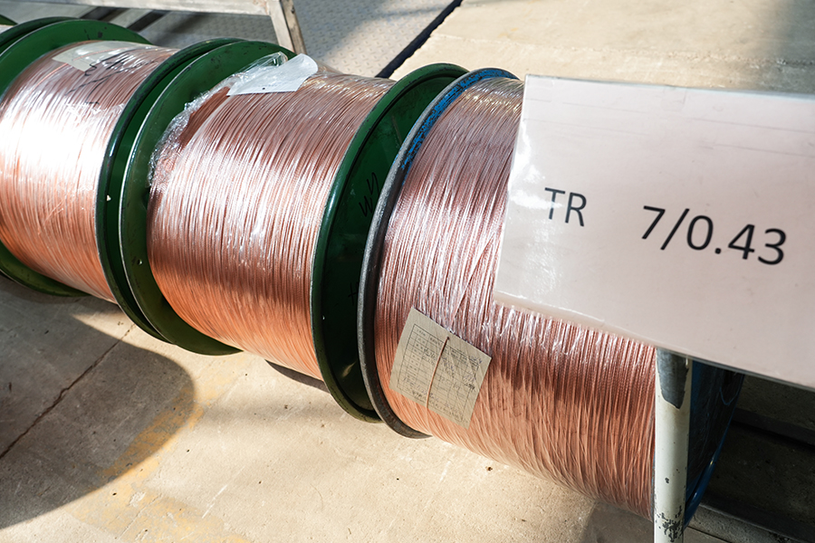
Single solid conductors serve low-flexibility applications (fixed wiring in walls). For flexible cables — appliance cords, portable tools, welding leads — multiple fine wires are twisted together in a stranding machine to form a stranded conductor. A typical AWG 12 stranded conductor uses 7 individual wires of AWG 22.5, twisted in a single layer around a central wire. Finer stranding (19, 37, or 133 wires) produces increasingly flexible conductors for demanding flex-cycle applications. The finished conductor then passes through an extruder — a heated barrel with a rotating screw — where thermoplastic or thermoset insulation material is melted and pressure-extruded over the conductor in a continuous coating.
Electrical Wire Insulation Types: Materials, Ratings, and Selection
Electrical wire insulation is the dielectric coating that prevents current from escaping the conductor, protects against environmental degradation, and — in many applications — provides mechanical protection and flame resistance. Insulation choice directly determines the wire's voltage rating, temperature rating, chemical resistance, and applicable installation environments. No single insulation material excels across all parameters, which is why dozens of insulation types exist across the wire industry.
PVC (Polyvinyl Chloride)
PVC is the most widely used wire insulation material globally, accounting for the majority of building wire, control cable, and appliance cord insulation by volume. It is inexpensive, easy to extrude, self-extinguishing (flame retardant grades), and resistant to oils, acids, and moisture. Standard PVC insulation is rated to 60°C or 75°C continuous operating temperature, with 90°C grades available. Its weakness is low-temperature performance — standard PVC becomes brittle below –10°C — and it releases hydrogen chloride gas when burned, which is corrosive and toxic. For this reason, PVC is prohibited in some building applications (plenum spaces, tunnels, public buildings) where toxic smoke is a life-safety concern. THHN and THWN building wire — the standard choice for residential conduit wiring in North America — use a nylon-jacketed PVC insulation rated 90°C dry / 75°C wet.
XLPE (Cross-Linked Polyethylene)
XLPE is produced by chemically or physically cross-linking polyethylene chains after extrusion, creating a three-dimensional polymer network that does not melt. This gives XLPE a continuous temperature rating of 90°C (dry) and 75°C (wet), with short-circuit withstand temperatures of 250°C — significantly better than PVC's 160°C short-circuit limit. XLPE has lower dielectric losses than PVC, making it the standard insulation for medium-voltage (1 kV–35 kV) and high-voltage power cables where dielectric heating in PVC would be problematic at operating frequency. USE-2 and RHW-2 building wire, rated for underground and wet locations, use XLPE insulation. The material does not release corrosive gases when burned, giving it a safety advantage over PVC in enclosed installations.
LSZH (Low Smoke Zero Halogen)
LSZH insulation uses halogen-free polymer compounds — typically polyolefin blends with mineral filler flame retardants — that produce minimal smoke and no halogenic acid gases when exposed to fire. This is critical in confined spaces where evacuation is difficult: tunnels, ships, offshore platforms, data centers, and mass transit systems. European building regulations (CPR — Construction Products Regulation) classify cables by reaction-to-fire performance, and LSZH formulations dominate the Cca, B2ca, and higher performance classes. The trade-off is mechanical toughness — LSZH compounds are generally softer and less abrasion-resistant than PVC, requiring more careful installation handling.
Silicone Rubber
Silicone rubber insulation covers the temperature extremes that thermoplastic insulations cannot reach: continuous ratings from –60°C to +180°C, with some grades withstanding 200°C for limited durations. Silicone is flexible even at cryogenic temperatures, chemically inert, UV-resistant, and non-toxic when burned. These properties make it standard for oven wiring, industrial furnace applications, medical equipment leads, and aerospace wiring. Cost is the primary limitation — silicone insulated wire costs 3–8× more per meter than equivalent PVC wire, which confines it to applications where its thermal performance is genuinely required.
PTFE (Polytetrafluoroethylene)
PTFE — commercially known as Teflon — provides the highest chemical resistance of any wire insulation, combined with a continuous temperature rating of 260°C and excellent dielectric properties at high frequencies. PTFE-insulated wire is standard in aerospace wiring harnesses (MIL-W-22759 and equivalent), high-frequency coaxial cables, and chemical processing equipment where aggressive solvents or acids would destroy any other insulation material. Its extremely low coefficient of friction and non-stick surface also make PTFE-insulated wire easier to pull through conduit and bundling in tight harnesses.
Types of Electrical Cable: Construction and Application
An electrical cable differs from a wire in that it combines multiple insulated conductors — plus often a ground wire, filler material, shielding, and an outer jacket — into a single assembly designed for a specific installation environment and electrical function. Cable construction is not interchangeable across applications: using the wrong cable type in a given environment can create fire hazards, code violations, or premature insulation failure.
NM-B (Non-Metallic Sheathed Cable)
NM-B — commonly called Romex, after the dominant brand — is the standard cable for residential wiring in dry, interior locations throughout North America. It consists of two or three insulated copper conductors (typically THHN) plus a bare ground wire, wrapped in a paper separator and enclosed in a PVC outer jacket. NM-B is available in 14/2, 12/2, 10/2 (two conductors plus ground) and 14/3, 12/3 (three conductors plus ground — required for three-way switch circuits). It is rated 90°C at the conductor but must be derated to 60°C ampacity in practice due to the outer jacket's heat retention. NM-B cannot be used in wet locations, embedded in concrete, or run exposed in areas subject to physical damage.
UF-B (Underground Feeder Cable)
UF-B cable is designed for direct burial in soil without conduit — the conductors are embedded in a solid gray PVC compound rather than wrapped in a separate jacket, creating a moisture-resistant, crush-resistant assembly. It is used for outdoor circuits (landscape lighting, outbuildings, garden outlets) and can also be used indoors in damp locations where NM-B is prohibited. Minimum burial depth under NEC is 24 inches for direct-buried UF-B without conduit protection, reduced to 12 inches when protected by conduit.
MC Cable (Metal-Clad Cable)
MC cable encloses insulated conductors in a flexible interlocked aluminum or galvanized steel armor, providing mechanical protection suitable for exposed runs in commercial and industrial buildings, and in residential applications where local codes prohibit NM-B (many urban jurisdictions and multifamily buildings). The armor is not a substitute for a ground conductor — MC cable includes a dedicated insulated equipment ground wire. MC cable is approved for use in wet locations (with listed fittings), in concrete, and in some direct-burial applications, offering installation flexibility that NM-B cannot match.
SE and SER Cable (Service Entrance)
Service entrance cable connects the utility meter to the main electrical panel. SE-R (service entrance, round) contains two insulated phase conductors and a bare aluminum neutral conductor, all jacketed in a braided or PVC outer covering rated for outdoor exposure. SER is used for the 100–400A feeds from the meter to the panel and for subpanel feeds within the same building. It is not approved for direct burial without conduit. For the utility service drop — the connection from the transformer to the meter — overhead triplex cable (pre-twisted aluminum conductors with XLPE insulation) is standard.
Armored and Screened Data Cables
Low-voltage data and communications cables — Cat6 Ethernet, coaxial RG-6, fiber optic with copper tracer — are electrical cables in the regulatory sense, subject to NEC Article 800 and 820. In plenum spaces (above dropped ceilings, in air-handling plenums), these cables must use CMP-rated (Communications Plenum) jackets with low-smoke, low-flame-spread properties. Riser-rated (CMR) cables are required in vertical runs between floors. Standard CM-rated cables are permitted only in non-plenum, non-riser interior spaces. Substituting riser cable in a plenum is a common and dangerous installation error that fails fire inspections and can cause toxic smoke to circulate through HVAC systems in a fire event.
What Type of Wiring Is Used in Homes Today?
Modern residential wiring in the United States follows a standardized system established by the NEC and enforced by local building codes. The materials, cable types, and circuit configurations in a home built or rewired after 2000 are substantially different from pre-1970s wiring, and understanding the current standard helps homeowners assess older wiring, plan renovations, and communicate with electricians.
Copper Conductor Throughout
All branch circuit wiring in new residential construction uses copper conductors. Aluminum wiring — used extensively in homes built between 1965 and 1973 due to a copper shortage and price spike — caused thousands of house fires due to its greater thermal expansion, tendency to oxidize at connections, and cold flow under screw terminals. Aluminum is still used today for service entrance conductors and large feeder cables (200A panels, subpanels, range and dryer circuits) where its lower cost per ampere-foot is significant and where connections are made with listed aluminum-compatible lugs rather than standard screw terminals.
NM-B Cable as the Primary Branch Circuit Wiring
The vast majority of branch circuits in a single-family home — general lighting, outlets, small appliances — are wired with NM-B cable routed through wall cavities, across joists, and stapled to framing. A typical new home contains 1,000–2,000 linear feet of NM-B cable across 20–40 branch circuits. Wire gauge follows circuit amperage: 14 AWG on 15A circuits (white-jacketed NM-B), 12 AWG on 20A circuits (yellow-jacketed), 10 AWG on 30A circuits (orange-jacketed). The jacket color coding is a standard adopted by manufacturers and widely recognized by inspectors but is not formally required by the NEC.
Dedicated Circuits for High-Load Appliances
The NEC requires dedicated circuits — circuits serving only a single outlet or appliance — for several high-load residential applications. A 20A, 120V dedicated circuit is required for each small appliance in the kitchen (minimum two circuits for countertop receptacles), the refrigerator, the dishwasher, the garbage disposal, and the microwave. Large appliances require 240V circuits: the electric range (50A, 8 AWG or 6 AWG), the clothes dryer (30A, 10 AWG), the central AC condenser (typically 30–60A depending on unit size), the electric water heater (30A, 10 AWG), and EV chargers (50A, 6 AWG for a 48A Level 2 EVSE). These 240V circuits use two-pole breakers and run 10/3 or 6/3 NM-B cable carrying both hot legs, a neutral, and a ground.
GFCI and AFCI Protection Requirements
Modern residential wiring code requires two types of supplementary protection beyond the standard breaker. GFCI (Ground Fault Circuit Interrupter) protection is required for all outlets in bathrooms, kitchens within 6 feet of a sink, garages, outdoor locations, crawl spaces, unfinished basements, and near swimming pools — any location where simultaneous contact with a grounded surface and a live conductor is plausible. GFCI devices detect current imbalance between hot and neutral as small as 4–6 milliamps and trip within 25 milliseconds, before cardiac fibrillation can occur. AFCI (Arc Fault Circuit Interrupter) protection is required by the 2017 and 2020 NEC editions for virtually all 15A and 20A branch circuits in living areas, bedrooms, hallways, and kitchens — detecting the high-frequency electrical signature of arcing faults in damaged wiring that standard breakers cannot sense.
Identifying Legacy Wiring in Older Homes
Homes built before 1940 may contain knob-and-tube wiring — individual cloth-insulated conductors routed through ceramic knobs and tubes, with no ground wire. This wiring is not inherently dangerous if undisturbed and unmodified, but it cannot support grounded outlets, is incompatible with modern appliances that require a ground, and is voided by most homeowner's insurance policies. Homes from the 1940s–1960s typically have two-wire circuits (no ground) with rubber-insulated conductors that have often become brittle. Both situations warrant evaluation by a licensed electrician before renovation or before adding circuits. Any home exhibiting cloth-wrapped wiring, two-prong ungrounded outlets throughout, or a fuse panel rather than circuit breakers should be assessed for rewiring — not to meet an arbitrary standard, but because the insulation degradation in 60–80-year-old wiring represents a genuine fire risk.


